Magnitude and Phase Representation
Fourier Transforms
The results of Fourier transform are usually complex numbers, which can be represented by its magnitude and phase
LTI Systems
With the property of LTI systems, if , we would have
This leads to
which implies we can first calculate and of the system and then use them to reconstruct . Here we call as the gain of this system, and as the phase shift of the system.
In particular, if a system have a unit gain, which means . The behavior of the system will be determined solely by it phase shift. We call this kind of system all-pass systems.
Linear and Non-linear Phase Shift
When the phase shift of the system is a linear function of , such as
This phase shift, in time domain, is represented by a time shift. This would not change the shape of the input signal.
However, if the phase shift of the system is non-linear, it could change the input signal a lot, which is not easy to predict. We can this phenomenon distortion.
Group Delay
To analyze time shift property in non-linear case, we consider a very narrow frequency interval near , where we can use a linear function of to approximate the real phase shift
In this case, we have
where the phase shift term is called the group delay of the system at , since in time domain this term can represent a time delay with . We can get the group delay by
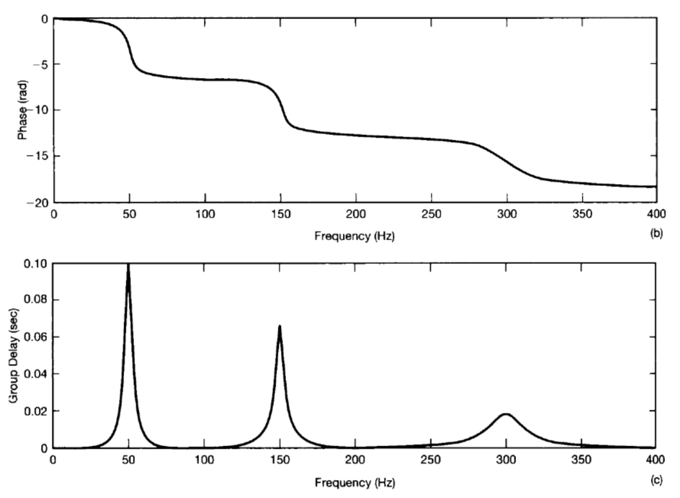 The figures above shows a and its . If we set the input signal as a unit impulse , we would have the response
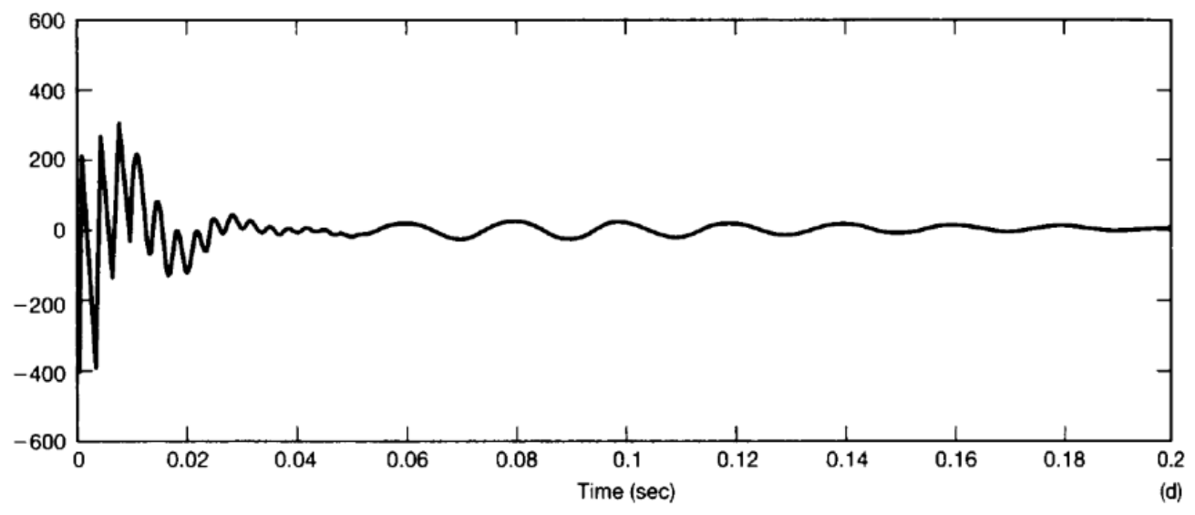 Recall that , which means that has the same value all through the frequency domain. However, due to the uneven group delay of the system, we could see the dispersion in the output. Since we have a maximum delay at , we see the output signal oscillates at as time goes on.
Logarithmic Magnitude and Phase Diagrams
Decibels
It is quite convenient to represent the magnitude using the log function, since
Therefore, if there is a Fourier transform of an input signal and the logarithmic magnitude and phase diagrams of the frequency response of a linear time-invariant system, the Fourier transform of the output can be obtained by adding the logarithmic magnitude diagrams and the phase diagrams of the two.
Similarly, since the frequency response of a cascaded LTI system is the product of the individual frequency responses, the total frequency response of a cascaded system in terms of logarithmic magnitude and phase diagrams can be obtained by adding the corresponding diagrams of the individual subsystems.
A logarithmic scale we use is expressed in a unit of , which is know as decibels(dB). Thus, dB corresponds to a frequency response magnitude of , dB corresponds to a gain of times, and dB corresponds to an attenuation of , and so on. Additionally, dB approximately corresponds to a gain of times, which is often useful to remember.
Bode Plot
The diagrams of and against are called Bode plots.
Time Domain Properties of Ideal Selective Filters
A continuous-time ideal low-pass filter has a frequency response of the following form:
This ideal low-pass filters have excellent frequency selectivity. That is, they pass below the cutoff frequency without attenuation, while completely blocking all frequencies in the blocking band. Furthermore, these filters have a zero-phase characteristic, so they do not induce rentals, and they do not induce rent distortion.
However, the impulse response of the ideal low-pass filter is
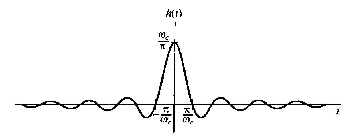 It should be noted that, in both the continuous-time and discrete-time cases, the passband width of the filter is directly proportional to , while the main lobe width of the unit impulse response is inversely proportional to . When the filter's bandwidth increases, the unit impulse response becomes narrower; conversely, the bandwidth decreases, the unit impulse response becomes wider.
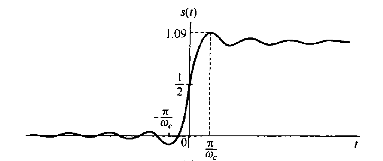
The unit step responses of the ideal low-pass filters are shown below. We can see that the step response exhibits several characteristics that we may not desire. In particular, for these filters, their step responses all have overshoots larger than their final steady-state values, and they exhibit oscillatory behavior known as ringing.
Time Domain Properties of Non-ideal Selective Filters
TODO